Making a part from your own model

The Parts dock has conveyors, sensors and other common equipment. For your own machine, you bring its model in from Blender or a CAD program and the simulator turns it into a part: a model with the right size, standing on the floor, with a solid shape that boxes and the walking character bump into.

In this guide you import a blade stop, the stop that rises between a conveyor's rollers to hold a box, then check it, name it and mount it under a roller conveyor. Its blade is a separate piece in the file, so it can be made to move later. The Parts dock already has a Blade Stop built from the same model, so you can compare your part with it. It takes about ten minutes.

You need

1. Prepare the model

With the example file, skip to step 2. With your own model, two things decide how much you can do with it later:

From Blender

  1. Select each object and apply its rotation and scale: Object > Apply > Rotation & Scale.
  2. Choose File > Export > glTF 2.0 (.glb/.gltf).
  3. Set Format to glTF Binary (.glb), and leave +Y Up ticked under Transform. Blender's Z up becomes the simulator's Y up.
  4. Export. Blender can also open .fbx, .obj and .stl files, so this is the way in for those too.

From a CAD program

Export the assembly as STEP. When you import it in step 2, the simulator converts it and asks four things first:

OptionChoose
Up axisPreset from the program that wrote the file. If the model comes in lying on its side, import it again with the other one.
Detailcoarse for a large assembly. It has about half the triangles.
Skip parts underA few millimetres leaves out screws and washers, which add nothing to a simulation.
Merge by colorOff if a piece will move later, so each solid stays a named piece. On draws a large assembly as a handful of meshes.

The script that tests this guide uses the example file, so the Blender and CAD steps above are not tested by it.

2. Import it

  1. In the Parts dock, click Import part. On the desktop it offers three choices: pick A model…. In a browser the file picker opens straight away.
  2. Pick your file. You can also drop it on the Parts dock instead.

The simulator makes a new part named after the file and opens it in the Part Editor, the view where you edit a part itself. The Inspector says what it did:

Imported blade-stop.glb. The part now fits the model: it stands on the floor, and its footprint and collider are the model's size.
The Inspector after the import, saying the part now fits the model: it stands on the floor, and its footprint and collider are the model's size.
The Inspector, right after the import.

The Scene dock now lists the part's two nodes:

NodeKindWhat it is
bodymeshYour model, moved so its underside is on the floor and it is centred on the part's origin.
colliderboxA hidden box the size of the model. Boxes on a belt and the walking character bump into this, not into the model.

The part's footprint, the box it snaps, selects and lands on the floor by, is the model's size too.

3. Check it

Click body in the Scene dock. Two sections of the Inspector show what is in the file.

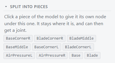
Split into pieces lists the named pieces and the groups that hold them. The example has eight pieces in two groups, Base and Blade. A piece you split out gets a node of its own, which can then get a joint: that is how a piece is made to move. If a piece you mean to move is not listed on its own, it is merged into another one in the file: split it in your 3D program and import again.

The Split into pieces section of the body node: the blade stop's eight pieces and its two groups, Base and Blade.
The example's pieces, and the two groups that hold them.

Mesh, opened with a click on its title, lists the materials. A material marked ⚠ renders dark is fully metallic with no texture, and draws nearly black. Lower its metalness in your 3D program. The example's four are fine.

Then check the size. Click collider in the Scene dock: its Box size is the model's, in metres. The example is 0.180 by 0.409 by 1.080: a housing 18 cm deep and 41 cm tall, for a blade 0.9 m wide.

If the size is 100 or 1000 times off, the model was exported in centimetres or millimetres. If it is lying on its side, it was exported with another up axis. Fix the export, select body, and use Import model… at the bottom of the Inspector to import it again. The part is fitted to the new file.

4. Name it

Click the part's own name at the top of the Scene dock, blade stop. The Inspector shows its Name and Category. The Parts dock already has a Blade Stop, so give yours a name of its own. Type these in, pressing Enter after each:

FieldType inMeaning
NameBlade Stop 900The name on its card in the Parts dock.
CategoryMy PartsThe Parts dock tab the card is under. A new name makes a new tab, which keeps your own parts together.
The Inspector for the part itself, with Name set to Blade Stop 900 and Category set to My Parts.
The part's name and category.

5. Mount it in a conveyor

A blade stop sits under a roller conveyor with its blade just below the rollers. Click ‹ Scene at the top of the Scene dock to go back to your scene, then:

  1. From the Equipment tab of the Parts dock, drag a Roller Conveyor into the view.
  2. From the My Parts tab, drag Blade Stop 900 into the view.
  3. Select each one and type these into the Inspector, in this order, pressing Enter after each:
PartFieldType inMeaning
Roller ConveyorStand Height0.8Its legs, for rollers 0.8 m off the floor.
Roller ConveyorWidth1Its frames 1 m apart, so the blade stop's ends sit under them.
Roller ConveyorPosition0, 0.8, 0X, Y and Z. A conveyor's Y is the top of its rollers.
Blade Stop 900Position0.5, 0.38, 0Under the conveyor, its blade across it.

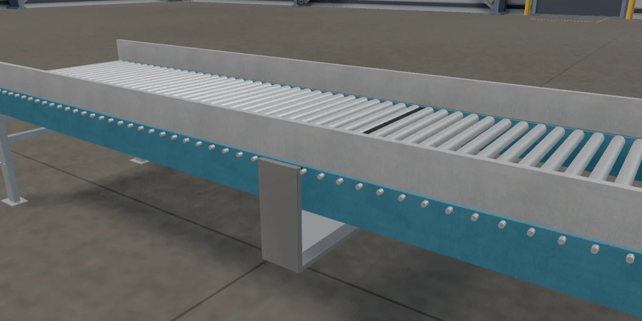
A part's Y is its underside, and the blade stop is 0.41 m tall, so at 0.38 the top of its blade is 1 cm below the rollers, where boxes pass over it. From above, the blade shows as a dark line between the rollers.

A roller conveyor with the blade stop mounted under it: the grey housing hangs below the conveyor's frame and the blade's top shows between the rollers.
Blade Stop 900, mounted under a roller conveyor.

Every copy you place is the same part. To change it later, right-click a copy, in the view or in the Scene dock, and choose Open Part Editor, and every copy in the scene changes with it. The part is saved with your project.

The collider is one box around the whole model, blade included, so mounted under the rollers it is out of the boxes' way. A blade that rises needs a collider of its own that rises with it, which the fourth guide adds.

Next: Making a piece move on a PLC command, where the blade rises when a program tells it to.

Troubleshooting

"... is not a model this importer can read."
The file has a model's name but not its contents, for example a .gltf file renamed to .glb. Nothing was changed. Export it again as glTF Binary, as in step 1. A .gltf with separate files, .fbx, .obj or .stl needs the same: open it in Blender and export a .glb.
The file picker does not show my file.
It lists only the files the simulator reads: .glb, .step, .stp, .usd, .usda, .usdc and .usdz. Convert anything else first.
The model is tiny, huge, or lying on its side.
The export's units or up axis are off. Fix them and import again on the body node, as in step 3.
Parts of the model are black.
Their material is fully metallic with no texture. The Mesh section marks it ⚠ renders dark. Lower its metalness in your 3D program.
The import says the model is heavy, or the scene slows down.
The model has more triangles than a simulation needs. Import a STEP file with Detail coarse and small parts skipped, a USD file with Detail reduced, or reduce it in Blender before you export.
Boxes catch on the blade stop, or it shows above the rollers.
Its Y is too high for the conveyor. Set it to the conveyor's Y minus 0.42, as in step 5.
The part is called "My Part" and shows a box.
You clicked + New part, which makes a blank part. Select its node and use Import model…, or start again with Import part.
I can't find the part in the Parts dock.
It is under the tab its Category names. Type its name in Search parts to find it in any tab.