Connecting an S7-1200 or S7-1500 over PUT/GET

An S7-1200 or S7-1500 CPU can let a client read and write its memory over the S7 protocol. The simulator uses this to write the sensors into the CPU's inputs and read its outputs back, while your program runs on the CPU. The CPU needs no extra hardware, license or OPC UA server.

The CPU only allows this once PUT/GET access is permitted in its configuration and that configuration is downloaded to it; step 3 lists what the CPU needs.

You need

1. Build the scene

In the desktop app, start a new scene and place three parts from the library:

  1. A Belt Conveyor.
  2. A Box, sitting on the belt near the end it starts from.
  3. A Photo Eye beside the belt, about two thirds of the way along, facing across it.

2. Wire the parts to addresses

Select each part, and in the Inspector's Comms group type its address:

PartFieldType inOn the CPU
Photo EyePresence Tag%IX100.0Input I100.0. The simulator writes it.
Belt ConveyorRun Tag%QX100.0Output Q100.0. The simulator reads it.
The Inspector's Comms group for the Photo Eye, with Presence Tag set to %IX100.0.
The photo eye's Comms group, wired to the CPU's input I100.0.

A part's address is the CPU's own address with a % in front and an X for a bit. Nothing is mapped or offset:

The simulator writes the photo eye into the CPU's input I100.0 and reads the belt's run bit from its output Q100.0. The CPU's program runs between them, reading I100.0 and writing Q100.0. The simulator writes I, reads Q Simulator Photo Eye %IX100.0 Belt Conveyor %QX100.0 CPU I100.0 Q100.0 PUT: write GET: read "Run" := NOT "Eye"; runs between
In the sceneOn the CPUThe simulator
%IXb.nIb.n, an input bitwrites it, that bit alone
%QXb.nQb.n, an output bitreads it
%IBn / %QBnIBn / QBn, a bytewrites / reads it
%IWn / %QWnIWn / QWn, a wordwrites / reads it
%IDn / %QDnIDn / QDn, a DINT or REALwrites / reads it
%MXb.n, %MWn, %MDnMemory Mwrites it if a part publishes it, reads it if a part is driven by it
DB1.DBX0.0, DB1.DBW2Data block 1, in the S7 data-block spelling, without the %the same as memory; see step 6

3. Set up the CPU

Configure and download the CPU in Siemens' own engineering software; its documentation shows where each setting lives. This guide needs the CPU to allow PUT/GET, to be reachable, and to run the program below.

3a. Allow PUT/GET

  1. The CPU permits PUT/GET access from a remote partner. Siemens names the setting Permit access with PUT/GET communication from remote partner, and a new CPU has it off.
  2. The CPU has an IP address this computer can reach. Note it for step 4; a new CPU is 192.168.0.1.
  3. The CPU sits in rack 0, slot 1, as every S7-1200 and S7-1500 does.

3b. The program

Add two PLC tags to the default tag table:

NameData typeAddress
EyeBool%I100.0
RunBool%Q100.0

and one line in Main [OB1], created in SCL (in LAD it is a normally closed contact on Eye driving a coil on Run):

"Run" := NOT "Eye";

3c. Download it

Download the CPU's configuration and the program, and put the CPU in RUN. The PUT/GET permission is part of the CPU's configuration, not of the program, so if the CPU is reset to factory settings or replaced, permit it and download the configuration again.

4. Point the simulator at the CPU

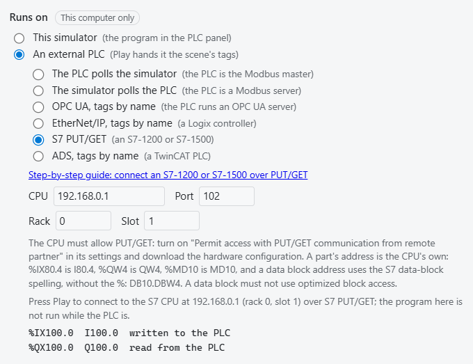
Open Simulation > PLC Controllers… and set:

  1. Runs on: An external PLC.
  2. Under it, how the PLC connects: S7 PUT/GET.
  3. CPU: the CPU's IP address from step 3a. It starts at 192.168.0.1, a new CPU's address.
  4. Port: 102, the port every S7 CPU answers on.
  5. Rack: 0 and Slot: 1, right for every S7-1200 and S7-1500.

The list underneath should read %IX100.0  I100.0  written to the PLC and %QX100.0  Q100.0  read from the PLC.

The External PLC settings: Runs on An external PLC, connecting with S7 PUT/GET, the CPU, Port, Rack 0 and Slot 1, the reminder to permit PUT/GET in TIA Portal, and the list: %IX100.0 I100.0 written to the PLC and %QX100.0 Q100.0 read from the PLC.
Set up for S7 PUT/GET, with the two addresses it will write and read.

The first time you press Play with a CPU on the network, the app asks whether to allow the connection: Allow Open Industry Project to connect to a PLC at 192.168.0.1:102? Choose Allow. The app remembers it for that address.

5. Run it

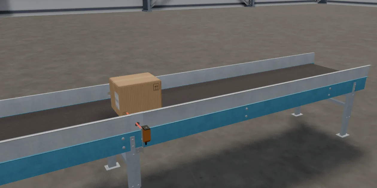
With the CPU in RUN, press Play. The status line says Reading and writing the CPU's memory at 192.168.0.1 (rack 0, slot 1) with a count of cycles, the box rides to the sensor, and the CPU stops the belt.

The belt conveyor with the box stopped in front of the photo eye, about two thirds of the way along.
The CPU stopped the belt when the photo eye saw the box.

If PUT/GET is still off

The CPU accepts the connection but refuses every read and write, and the status line says Waiting for the PLC at 192.168.0.1 (rack 0, slot 1): the CPU refused a write of I100.0 (error 0x8104): the CPU does not allow it. On an S7-1200/1500 that means PUT/GET is off, then where the checkbox is. Leave the simulation running, permit PUT/GET as in step 3a, and download the CPU's configuration. The simulator asks again every second, so the belt starts once the CPU allows it.

6. A data block instead of inputs

A program written for simulation often keeps its simulated signals in a data block rather than on input addresses. That works too, with one more setting that every new data block has the wrong way round: Optimized block access. An optimized block has no fixed byte offsets, so PUT/GET cannot address it.

  1. Add a global data block, DB1, with a Bool Eye as its first variable.
  2. Turn off optimized block access for the data block, so its variables have fixed byte offsets (Siemens' documentation shows where), and compile. Eye is then at offset 0.0.
  3. Read it in Main [OB1] instead of the input (the data block's name in place of "DB1" if you gave it one):
"Run" := NOT "DB1".Eye;
  1. Download, then rewire the photo eye in the simulator to the data block, in the S7 data-block spelling, without the %:
PartFieldType inOn the CPU
Photo EyePresence TagDB1.DBX0.0DB1, byte 0, bit 0: "DB1".Eye

If the block is still optimized, the CPU refuses the photo eye's writes, so nothing reaches the program and the belt never starts. The status line says Waiting for the PLC at ...: the CPU refused a write of DB1.DBX0.0, then A data block read or written over PUT/GET must exist and must NOT use optimized block access and where the setting is. Untick it, compile, download, and run again.

Troubleshooting

The connection options are greyed out.
You are in a browser tab. Connecting to a PLC needs the desktop app.
"Waiting for the PLC at ...: nothing is listening"
Nothing answered on port 102 at that address. Check the CPU's IP address, that this computer is on the same subnet, and that the CPU is powered. The simulator tries again every second.
"... the CPU does not allow it ... PUT/GET is off"
Permit PUT/GET on the CPU and download the CPU's configuration, not only the program. See step 3.
"... (rack 0, slot 1 for an S7-1200 or S7-1500)"
The CPU refused or closed the connection before it was set up, because the rack or slot is wrong. Set Rack 0 and Slot 1.
It connects, but the belt never stops.
The eye's address is on a real input module, which the CPU copies over the simulator's value every cycle. Move it to a byte no module occupies, in the scene and in the PLC tag. Watching "Eye" online in the engineering software shows whether it ever turns true.
"... must NOT use optimized block access"
The data block still has Optimized block access ticked, so its variables have no offsets to read or write, and the belt never starts. See step 6.
A part's address is not listed.
The dialog lists what it cannot carry, and why: a 64-bit (%IL) address, for example, does not travel.