Connecting to a PLC's Modbus or OPC UA server

Many PLCs do not poll remote I/O over Modbus. They publish their I/O on a Modbus TCP server, or their variables on an OPC UA server, and the simulator connects to them as a client. It writes the sensor values to the PLC and reads the motor outputs back, while your program runs on the PLC.

This guide covers both with the same belt, box and sensor. Part A connects by address over Modbus TCP and part B by name over OPC UA. Any PLC or soft PLC that runs such a server will do; how to add the server to it is in that PLC's own documentation.

You need

1. Build the scene

In the desktop app, start a new scene and place three parts from the library:

  1. A Belt Conveyor.
  2. A Box, sitting on the belt near the end it starts from.
  3. A Photo Eye beside the belt, about two thirds of the way along, facing across it.

Select the sensor and the belt, and find the Comms group in the Inspector. What you type into their tag fields depends on the connection, so it is in part A and part B.

Part A. Modbus TCP

A PLC's Modbus server device exposes its process image as registers. The simulator writes holding registers, which the PLC reads as its inputs (%I), and reads input registers, which hold its outputs (%Q). A bit sits inside a register.

A1. Wire the parts to addresses

PartFieldType inOn the PLC's server
Photo EyePresence Tag%IX0.0Holding register 0, bit 0
Belt ConveyorRun Tag%QX0.0Input register 0, bit 0

A2. Point the simulator at the PLC

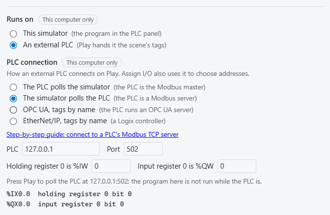
Open Simulation > PLC Controllers… and set:

  1. Runs on: An external PLC.
  2. Under it, how the PLC connects: The simulator polls the PLC (the PLC is a Modbus server).
  3. PLC: 127.0.0.1 if the PLC runs on this computer, otherwise its address. Port: 502, unless its server device listens elsewhere.
  4. Holding register 0 is %IW and Input register 0 is %QW: where the PLC's server device puts its first register in the PLC's memory. The PLC's own configuration of the device says where; both are often 0 when the device is the PLC's only I/O.

The list underneath should read %IX0.0  holding register 0 bit 0 and %QX0.0  input register 0 bit 0. The rule is that %IWn is holding register n counted from that base, and %IXb.n is bit (b mod 2)×8 + n of the register holding byte b. A REAL (%ID) takes two registers, low word first.

The External PLC settings: Runs on An external PLC, connecting with The simulator polls the PLC, PLC 127.0.0.1, Port 502, both register bases 0, and the list: %IX0.0 holding register 0 bit 0 and %QX0.0 input register 0 bit 0.
Set up to poll the PLC's Modbus server, with the two points it will read and write.

A3. The PLC program

PROGRAM PLC_PRG
VAR
  Eye AT %IX0.0 : BOOL;
  Run AT %QX0.0 : BOOL;
END_VAR

Run := NOT Eye;
END_PROGRAM

These are the same addresses as the scene, because on this kind of PLC the simulator and the PLC share one process image.

On the PLC

  1. Add a Modbus TCP server device to the PLC's configuration, in whatever form its engineering tool offers one (a soft PLC such as CODESYS Control Win is one place such a device can live). Note the port it listens on, and use the same number in the simulator.
  2. Find where the device maps its holding registers and its input registers in the PLC's memory. Those are the two base addresses for the simulator. Make sure the device maps at least as many registers as the scene uses.
  3. Put the program above into the PLC, in a task that runs it cyclically, then download it and start it.

The vendor's documentation says how to do each of these in its tool.

A4. Press Play

The status line says Polling the PLC at 127.0.0.1:502 with a count of requests, the box rides to the sensor, and the PLC stops the belt. Press Play before the PLC is up and it waits: Waiting for the PLC at 127.0.0.1:502: ... Trying again every second.

Stop the application on the PLC while the box is moving and the belt stops. A Modbus server device goes quiet when its application stops, and about a second later the simulator holds every output the PLC drives off until it answers again, and the status line says The PLC at 127.0.0.1:502 stopped answering for 1.0 s: its outputs are held off until it answers again.

Part B. OPC UA

OPC UA carries names, not addresses, so nothing is mapped. Each part's tag is the PLC's own name for the variable, and the simulator finds it on the server. Stop the simulation before you rewire.

B1. Wire the parts to the PLC's names

PartFieldType inThe PLC's variable
Photo EyePresence TagPLC_PRG.EyeThe simulator writes it
Belt ConveyorRun TagPLC_PRG.RunThe simulator reads it

The simulator matches a tag against the end of each variable's path on the server, so PLC_PRG.Eye finds a variable at .../PLC_PRG/Eye whatever folders the server puts above it, and the same idea works for MAIN.Eye or any other program name. Case does not matter; a name that fits two variables is refused with both listed.

B2. Point the simulator at the server

In Simulation > PLC Controllers…:

  1. Runs on: An external PLC.
  2. Under it, how the PLC connects: OPC UA, tags by name (the PLC runs an OPC UA server).
  3. Server: the PLC's endpoint, opc.tcp://127.0.0.1:4840 on the same computer by default.

The connection is unsecured, with security policy None and an anonymous login, so the PLC's server has to allow both. Use it on a test bench, not a plant network.

On Play the simulator reads the server's whole tree under Objects to find each tag. If the server holds far more than the program, as a controller that also runs a CNC or drives does, put where the program's variables are in Browse from: a path from Objects like DeviceSet.PLC.Programs, or a NodeId, several separated by commas. Tags keep the names they have; only less of the tree is read.

B3. The PLC program

PROGRAM PLC_PRG
VAR
  Eye : BOOL;
  Run : BOOL;
END_VAR

Run := NOT Eye;
END_PROGRAM

Eye is a plain variable, not an input at %IX, because most PLCs refuse a client's write to a real input, which their I/O system overwrites every scan.

On the PLC

  1. Put the program above into the PLC, as in part A or in a project of its own.
  2. Publish Eye and Run on the PLC's OPC UA server, readable and writable. Every PLC has its own way to choose which variables its server exports; its documentation says how.
  3. Download the program and start it.

B4. Port 4840 may not be the PLC

4840 is OPC UA's standard port, and some OPC software installs the OPC Foundation's discovery server there. It is a directory of the computer's OPC UA servers, with no tags. If that is what answers, the simulator says so on Play instead of reporting every tag missing: Could not connect: opc.tcp://127.0.0.1:4840 is an OPC UA discovery server, not a PLC, followed by the servers it knows of, if any. A PLC's server that does not register with it will not be among them.

Move the PLC's server to its own port, such as 4841, in the PLC's own configuration (its documentation says where), and restart it. Then use opc.tcp://127.0.0.1:4841 as the Server.

B5. Press Play

The status line says Reading and writing the PLC's tags at opc.tcp://127.0.0.1:4840 (or the port you moved the server to), the dialog lists each tag against the variable it found, and the PLC stops the box at the sensor.

A stopped program can still look alive. An OPC UA server belongs to the runtime, not the program, and keeps answering with the last values when the application stops. Only a lost connection, or a server that goes silent, makes the simulator hold the PLC's outputs off.

Troubleshooting

The connection options are greyed out.
You are in a browser tab. Connecting to a PLC needs the desktop app.
"Waiting for the PLC at ...: nothing is listening"
The PLC is not running, or not at that address and port. The simulator tries again every second, so start the PLC and it connects.
Modbus: it polls, but the belt never runs or never stops.
The base addresses do not match the server device's I/O mapping, or the scene uses a register the device does not map (check how many registers the device is set to map each way). The dialog lists the register each point uses.
OPC UA: a tag is "not found".
The variable is not published. Check which variables the PLC's OPC UA server exports, then rebuild and download.
OPC UA: a tag is read only.
The simulator writes the sensors, so their variables must be writable, which means a plain variable rather than a located input.
OPC UA: connecting takes long, or "a branch of the PLC's tags did not answer in time".
The server's tree is large, or part of it answers slowly. Set Browse from (see B2) to the folder that holds the program's variables.
OPC UA: "the PLC has no ... to browse from".
A Browse from path does not match the server's tree. Check the names under Objects in an OPC UA browser, or give the folder's NodeId.
OPC UA: "... is an OPC UA discovery server, not a PLC".
The PLC's server is on another port. See B4.