6. Analog values (optional)
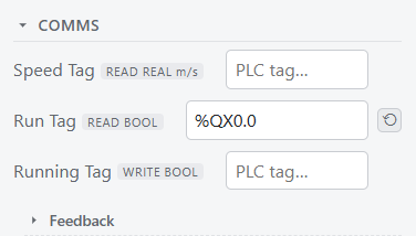
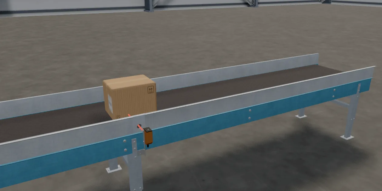
A REAL travels in two registers. Add a Laser Sensor beside the belt, before the Photo Eye, and wire
two more fields:
Then slow the belt down while the laser sees a box within a metre:
PROGRAM main
VAR
  Eye   AT %IX0.0 : BOOL;
  Run   AT %QX0.0 : BOOL;
  Range AT %ID50 : REAL;    (* metres to the box *)
  Speed AT %QD50 : REAL;    (* belt speed, m/s *)
END_VAR

Run := NOT Eye;
IF Range > 0.0 AND Range < 1.0 THEN
  Speed := 0.1;
ELSE
  Speed := 0.5;
END_IF;
END_PROGRAM
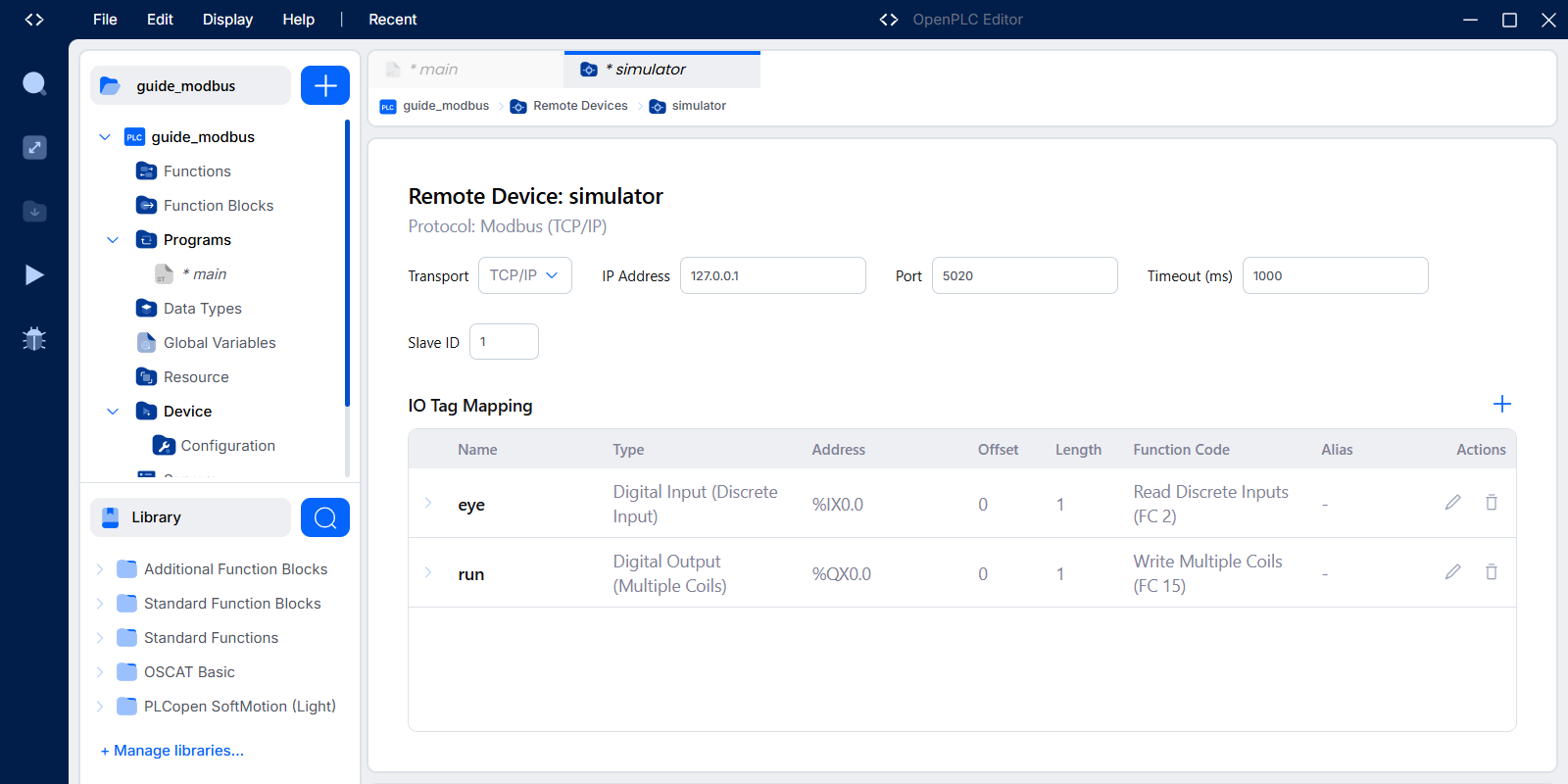
On the PLC, add a group that reads input registers from 100, two long, into %ID50, and one that writes
holding registers from 100, two long, from %QD50. Set the master to low word first.
The OpenPLC Editor (4.3.0) cannot set this step up through its screens. An IO group maps each
register to its own 16-bit word (%IW, %QW) and has no option for a REAL across two. The
OpenPLC Runtime itself reads and writes REALs this way, low word first, which is how this step is tested, but
that takes a hand-written device file rather than the Editor's Remote Device page.
The Range > 0.0 check is there because the PLC's first scan can run before its first poll, so an analog input
reads 0 for a scan or two after start, and 0 looks like a real measurement. Inside the simulator this never
happens, because inputs are loaded before the first scan. A real PLC needs the guard, and so does the program
you will eventually put on one.